Graco 310564D User Manual
Browse online or download User Manual for Power fine-spray systems Graco 310564D. Graco 310564D User's Manual
- Page / 30
- Table of contents
- TROUBLESHOOTING
- BOOKMARKS
- Packages 1
- Table of Contents 2
- List of Models 2
- Warning Symbol 3
- Caution Symbol 3
- EQUIPMENT MISUSE HAZARD 3
- PRESSURIZED EQUIPMENT HAZARD 3
- MOVING PARTS HAZARD 4
- FIRE AND EXPLOSION HAZARD 4
- TOXIC FLUID HAZARD 4
- Component Identification 5
- Site Preparation 6
- Supplied Components 6
- Connect the Fluid Lines 8
- Connect the Air Line 8
- Using the Quick Connectors 8
- Grounding 9
- Operation 10
- Maintenance 13
- Troubleshooting 15
- 4:1 Ratio, Glutton Pump 16
- Left Hand Mount Model: 96A638 18
- Model 618613 24
- 9/16 in. (4) places 24
- 3/8 in. (8) places 24
- 24 310564 24
- 310564 25 25
- Model 618314 25
- Technical Data 26
- 310564 27 27
- Dimensions 28
- Mounting Hole Layout 29
- Graco Standard Warranty 30
- Graco Information 30
Summary of Contents
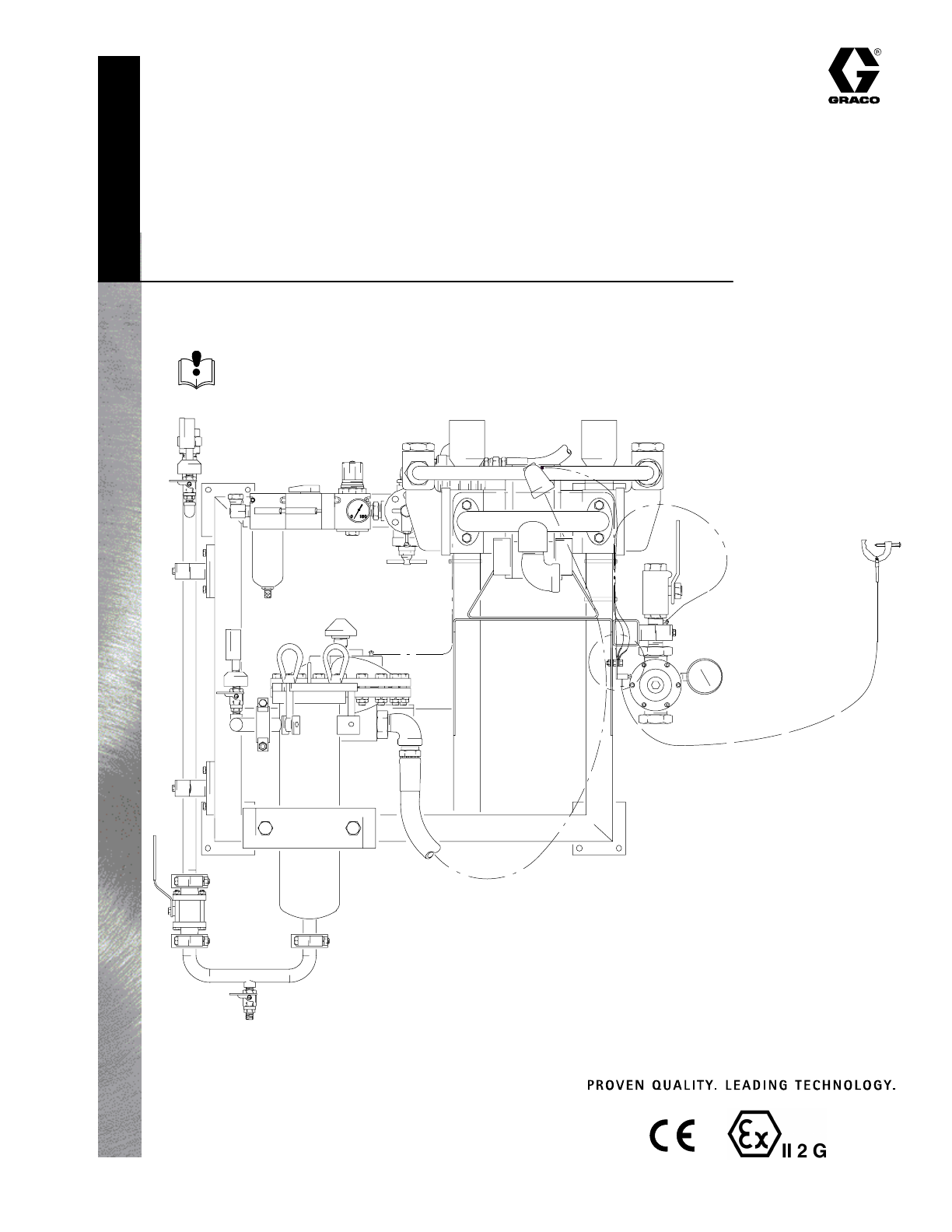
Instructions – Parts ListGRACO INC.ąP.O. BOX 1441ąMINNEAPOLIS, MNą55440-1441Copyright 2002, Graco Inc. is registered to I.S. EN ISO 9001WALL MOUNT OR
10 310564OperationPressure Relief ProcedureWARNINGPRESSURIZED EQUIPMENT HAZARDThe system pressure must be manually relieved toprevent the system from
310564 11OperationTI0957Fig. 4Model 96A637 ShownSide View23 Ref514 RefBBAA CCDDWY2314
12 310564OperationStarting and Adjusting the Pump1. Fig. 4. Open all fluid shutoff valves (5–two). Makesure Air Regulator (CC) is fully closed.2. Open
310564 13MaintenancePreventive Maintenance ScheduleThe operating conditions of your particular systemdetermine how often maintenance is required. Esta
14 310564MaintenanceAir Filter Service1. Fig. 4. Every day, drain contaminants from thebowl before reaching the baffle level by openingthe drain at th
310564 15TroubleshootingWARNINGTo reduce the risk of serious injury whenever you are instructed to relieve pressure, always followthe Pressure Relief
16 310564PartsRight Hand Mount Model: 96A6374:1 Ratio, Glutton PumpTI09571113141454,3245,4,3141953,21,2012,4,3221351735 503645434,3,21151617233,414 Re
310564 17PartsRight Hand Mount Model: 96A6374:1 Ratio, Glutton PumpRef PartNo. No. Description QtyRef PartNo. No. Description Qty1 618216 FRAME, wall/
18 310564PartsLeft Hand Mount Model: 96A6384:1 Ratio, Glutton PumpTI09581113141453,4243,4,5141920,21,533,4,12221351735503645432,3,4115161723 3,4 14 Re
310564 19PartsLeft Hand Mount Model: 96A6384:1 Ratio, Glutton PumpRef PartNo. No. Description QtyRef PartNo. No. Description Qty1 618216 FRAME, wall/f
2 310564Table of ContentsList of Models 2. . . . . . . . . . . . . . . . . . . . . . . . . . . . . . . . . . Warnings 3. . . . . . . . . . . . . . . .
20 310564PartsRight Hand Mount Dual Filter Model: 96A9384:1 Ratio, Glutton PumpTI09591113141454,3245,4,3141953,21,2012,4,3221351735 503645434,3,211516
310564 21PartsRight Hand Mount Dual Filter Model: 96A9384:1 Ratio, Glutton PumpRef PartNo. No. Description QtyRef PartNo. No. Description Qty1 618380
22 310564PartsLeft Hand Mount Dual Filter Model: 96A9394:1 Ratio, Glutton PumpTI09601113141453,4243,4,5141920,21,533,4,12221351735503645432,3,41151617
310564 23PartsLeft Hand Mount Dual Filter Model: 96A9394:1 Ratio, Glutton PumpRef PartNo. No. Description QtyRef PartNo. No. Description Qty1 618381 F
24 310564PartsSingle Mount Floor Stand, Model 618613 Model 6186139/16 in. (4) places3/8 in. (8) placesTI0999
310564 25PartsDual Mount Floor Stand, Model 618314 Model 6183149/16 in. (4) places3/8 in. (8) placesTI1000
26 310564Technical Data4:1 Ratio Glutton PumpsCategory DataMaximum Fluid Working Pressure 2.4 MPa, 24.5 bar (350 psi)Air Operating Range 0.17–0.6 MPa,
310564 27Notes
28 310564DimensionsMount the circulation package so the top of thebracket is 5 to 6 ft (1.5 to 1.8 m) above the floor.1Ensure that there is 5 ft (1.5
310564 29Mounting Hole Layout1Check that the wall frame is level before bolting it to the wall.2Mount the wall frame so the top edge is 5 to 6 ft (1.5
310564 3SymbolsWarning SymbolWARNINGThis symbol alerts you to the possibility of seriousinjury or death if you do not follow the instructions.Caution
30 310564Graco Standard WarrantyGraco warrants all equipment manufactured by Graco and bearing its name to be free from defects in material and workma
4 310564WARNINGMOVING PARTS HAZARDMoving parts, such as the air motor piston, can pinch or amputate your fingers.D Keep clear of all moving parts when
310564 5Component IdentificationTI0957Fig. 1Model 96A637 ShownKEYA Pump InletB Fluid Gauge and DampenerC Fluid Gauge Ball ValveD Fluid FilterE Filter
6 310564SetupWARNINGTo reduce the risk of serious injury whenever youare instructed to relieve pressure, always follow thePressure Relief Procedure on
310564 7SetupWARNINGTo reduce the risk of serious injury whenever youare instructed to relieve pressure, always follow thePressure Relief Procedure on
8 310564SetupConnect the Fluid LinesFig. 1. Connect system fluid supply line to the circula-tion package at fluid supply inlet (A). Close filter ballv
310564 9SetupGroundingWARNINGFIRE AND EXPLOSION HAZARDBefore operating the circulation pack-age, ground the system as explainedbelow. Also read the s
Related products and manuals for Power fine-spray systems Graco 310564D
 (48 pages)
© 2020, manymanuals.com. All rights reserved. | 1.252 s |
 Manymanuals.com
 Manymanuals.de
 Manymanuals.fr
 Manymanuals.it
 Manymanuals.pl
 Manymanuals.cz
 Manymanuals.es
 Manymanuals-pt.com
Comments to this Manuals