Graco 308395D User Manual
Browse online or download User Manual for Unknown Graco 308395D. Graco 308395D User's Manual
- Page / 14
- Table of contents
- TROUBLESHOOTING
- BOOKMARKS
- Hydraulic Fluid 1
- Controls 1
- Warnings 2
- 308395D 3 3
- Installation 4
- Typical Installation 5
- Installation Notes 6
- Hydraulic Power Supply 6
- Hydraulic Components 6
- Operation 7
- Shutdown 8
- Pressure Control Repair 8
- Flow Control Repair 8
- Troubleshooting 9
- 10 308395D 10
- 308395D 11 11
- Technical Data 12
- Dimensions 12
- 308395D 13 13
- Graco Standard Warranty 14
- Graco Information 14
Summary of Contents
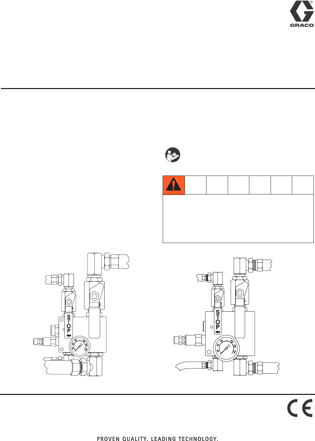
InstructionsHydraulic Fluid Controls308395DENRegulates hydraulic pressure and flow when used with Graco’s Dyna-Star™ and Power-Star™ hydraulic-powered
Parts 10 308395DPartsModel 236864 Hydraulic Fluid Control113a113b111105104108109106102112107113Includes items113a & 113b1031110110103Ref. Part Des
Parts308395D 11Model 236865 Hydraulic Fluid Control113b107102105106103112113109104113a108Includes items113a & 113b111111110110Ref. Part Descriptio
Technical Data 12 308395DTechnical DataDimensionsHydraulic Fluid Controls: Dyna-Star™US MetricMaximum fluid working pressure 1500 psi 10.5 MPa, 105 b
Notes308395D 13Notes
All written and visual data contained in this document reflects the latest product information available at the time of publication. Graco reserves th
Warnings 2 308395DWarningsThe following warnings are for the setup, use, grounding, maintenance, and repair of this equipment. The exclama-tion point
Warnings308395D 3EQUIPMENT MISUSE HAZARDMisuse can cause death or serious injury.• Do not operate the unit when fatigued or under the influence of dru
Installation 4 308395DInstallation GroundingPump: use ground wire and clamp (supplied). Loosen grounding lug locknut (W) and washer (V). Insert one en
Installation308395D 5Typical InstallationKey:A Hydraulic Control, 236864B Hydraulic Control, 236865C Hydraulic Return LineD Hydraulic Outlet, 3/4 npsm
Installation 6 308395DInstallation Notes• Blow out all hydraulic lines with air, flush thoroughly with solvent, and then blow out the air again before
Operation308395D 7OperationPressure Relief ProcedureFollow the Pressure Relief Procedure whenever you see this symbol.1. Close the supply line shutoff
Repair 8 308395DShutdown Always shut off the supply line shutoff valve (E) first, and then the return line shutoff valve (G). This is to prevent over
Troubleshooting308395D 9TroubleshootingProblem Cause SolutionNo pressure on gauge, or low pres-sure on gaugeHydraulic power supply malfunction or mis-
Related products and manuals for Unknown Graco 308395D
 (44 pages)
(54 pages)
(14 pages)
(1 pages)
(16 pages)
(14 pages)
(20 pages)
(12 pages)
(34 pages)
(52 pages)
(14 pages)
(44 pages)
(54 pages)
(14 pages)
(1 pages)
(16 pages)
(14 pages)
(20 pages)
(12 pages)
(34 pages)
(52 pages)
(14 pages)

 (12 pages)
(30 pages)
(1 pages)
(34 pages)
(2 pages)
(42 pages)
(12 pages)
(30 pages)
(1 pages)
(34 pages)
(2 pages)
(42 pages)
© 2020, manymanuals.com. All rights reserved. | 1.355 s |
 Manymanuals.com
 Manymanuals.de
 Manymanuals.fr
 Manymanuals.it
 Manymanuals.pl
 Manymanuals.cz
 Manymanuals.es
 Manymanuals-pt.com
Comments to this Manuals