Graco 3A2497BPro User Manual
Browse online or download User Manual for Paint Sprayer Graco 3A2497BPro. Graco 3A2497BPro User's Manual
- Page / 78
- Table of contents
- TROUBLESHOOTING
- BOOKMARKS
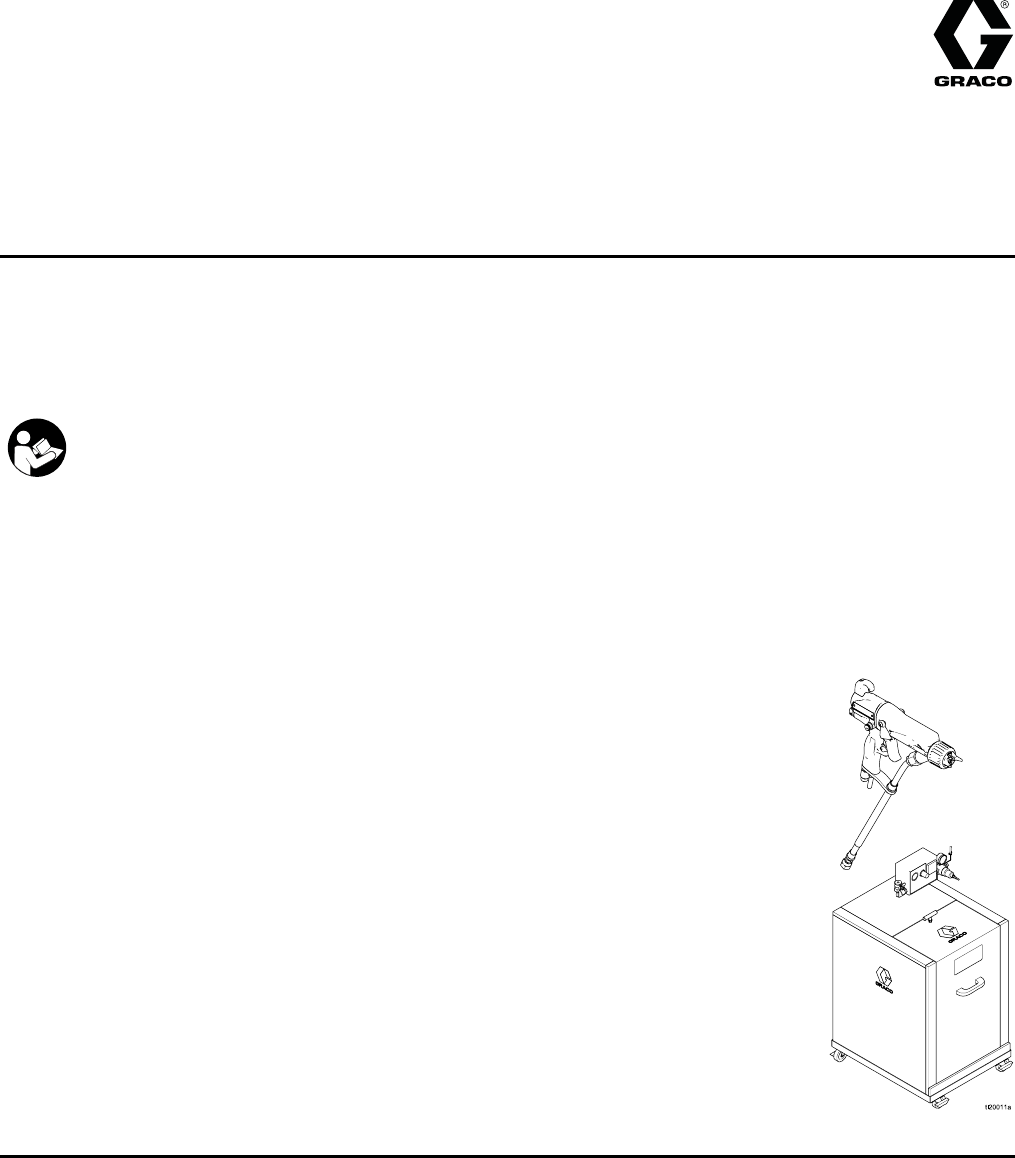
- WB3000 Isolation System & 1
- Pro Xp™ 60 AA WB Gun 1
- Contents 2
- 3A2497B 3 3
- Warnings 4
- 3A2497B 5 5
- 6 3A2497B 6
- Gun Overview 7
- Controls, Ind 8
- Smart Guns 9
- Error Display 10
- Lock Symbol 10
- Diagnostic Mode 13
- Current (microAmperes) Screen 13
- Low Voltage Lock Screen 14
- Installation 15
- Ground the Cabinet 16
- Air Supply Lin 16
- Connect the Wa 17
- 18 3A2497B 18
- 3A2497B 19 19
- Agitator Kit Accessory 20
- Gun Setup 21
- Check Gun Elec 23
- Flush Before Using Equipment 24
- Operation 25
- Pressure Reli 26
- Fill the Fluid 27
- Adjust the Spr 28
- 3A2497B 29 29
- Shutdown 30
- Maintenance 31
- 32 3A2497B 32
- Clean the Gun D 33
- 34 3A2497B 34
- Daily System C 35
- Electrical Tests 36
- Test Power Sup 37
- Test Gun Barre 38
- Test Ground St 39
- Test Cylinder 39
- Resistance 39
- Troubleshooting 40
- Visual Checks 41
- Spray Pattern 43
- Gun Operation 44
- Electrical Troubleshooting 45
- 46 3A2497B 46
- Prepare the Gun for Service 47
- Air Cap, Spray 48
- Tip, and Fluid Seat 48
- Housing Replacement 48
- Electrode Replacement 49
- Gun Barrel Rem 50
- Gun Barrel Ins 50
- Fluid Needle Replacement 51
- Power Supply R 52
- 3A2497B 53 53
- 54 3A2497B 54
- 3A2497B 55 55
- ES On-Off Valv 56
- Air Valve Repair 57
- Smart Module R 58
- Air Swivel and 59
- Exhaust Valve Replacement 59
- 60 3A2497B 60
- 3A2497B 61 61
- Smart Air-Ass 62
- 3A2497B 63 63
- Isolation Enclosure 64
- 3A2497B 65 65
- 66 3A2497B 66
- Alternator Assembly 67
- Fan Air Valve Assembly 69
- Air Cap Assemb 70
- Smart Module A 70
- Spray Tip Sele 71
- AEF Fine Finis 72
- Repair Kits, Related 73
- Manuals, and Accessories 73
- Test Equipment 74
- 245895 Agitat 75
- Dimensions 76
- Technical Data 77
- Graco Pro Xp Warranty 78
Summary of Contents
Instructions - PartsWB3000 Isolation System &Pro Xp™ 60 AA WB Gun3A2497BENAir-assisted spray system for use when electrostatically spraying conduc
Gun OverviewError DisplayIf the Smart module loses communication withthe power supply, the Error display appears, theHz indicator turns red, and the S
Gun OverviewTable 1 . Key for Figs. 2–9.Item Description PurposeVAVoltage Adjustment SwitchTwo-positionswitch sets smartgun voltage tolow setting (LO)
Gun OverviewItem Description PurposeCI Current IndicatorIn Diagnostic Mode, the twobottom right LEDs of the screenlight, indicating that the valuedisp
Gun OverviewDiagnostic ModeDiagnostic Mode includes four screens which displaygun data:• Voltage (kiloVolts) Screen• Current (microAmperes) Screen• Al
Gun OverviewAlternator Speed (Hertz) ScreenThe Alternator Speed (Hertz) Screen is the thirdscreen in the Diagnostic Mode. See Fig. 8, and Table1 on pa
InstallationInstallationSystem RequirementsAGracovoltage isolation system must have thefollowing features:• An isolation enclosure that prevents perso
InstallationAir Supply Line1. See Fig. 12. Install an air line filter/waterseparator (M) on the main air supply line toensure a dry, clean air supply t
InstallationConnect the Waterborne Fluid HoseAlways use a Graco waterborne fluid hose betweenthe voltage isolation system fluid outlet and the gunfluid i
InstallationFigure 12 Typical Installation, Pro Xp WaterborneSystem18 3A2497B
InstallationTypical Installation KeyItem DescriptionAMain Air Supply LineB* Bleed-Type Air ShutoffValveCPump Air PressureGaugeD Pump Air PressureRegul
ContentsModels... 3Warnings ... 4G
InstallationAgitator Kit AccessoryTo add an agitator to the Graco isolation system, orderPart No. 245895. See 245895 Agitator Kit, page 75,for the kit
Gun SetupGun SetupGroundingWhen operating the electrostatic gun, anyungrounded objects in the spray area (people,containers, tools, etc.) can become e
Gun Setup•The floor of the spray area:must be electricallyconductive and grounded. Do not cover the floorwith cardboard or any non-conductive materialwh
Gun SetupCheck Gun Electrical GroundingMegohmmeter Part No. 241079 (AA-see Fig.14) is not approved for use in a hazardous area.To reduce the risk of s
Gun Setup7. If the resistance is greater than 100 ohms, checkthe tightness of the ground connections and besuretheairhosegroundwireisconnectedtoatrue
OperationOperationOperating ChecklistCheck the following list daily, before starting thesystem.⃞All operators are properly trained to operatean electr
OperationPressure Relief ProcedureThis equipment stays pressurized until pressureis manually relieved. To help prevent seriousinjury from pressurized
OperationFill the FluidSupply1. Follow the Fluid Voltage Discharge andGrounding Procedure, page 25.2. Follow the Pressure Relief Procedure, page 26.3.
OperationAdjust the Spray PatternTo reduce the risk of fire and explosion, fluids usedmust meet the following flammability requirements:• FM, FMc Approve
Operation3. Check gun resistance. SeeTest Gun Resistance, page 36.4. Follow all steps under Grounding, page 21.5. Follow all steps underCheck Gun Elec
ModelsModelsModels which are FM Approved and Compliant with EN50059FM approved for use with fluids that meet the following condition:• Material does no
Operation16. Check that the ES indicator (Hz indicator onSmart guns) is lit, or check that the kV indicatoron the isolated enclosure reads 30–50 kV.Th
MaintenanceMaintenanceFlushing•Flushbeforechanging fluids, before fluid can dryin the equipment, at the end of the day, beforestoring, andbefore repairi
Maintenance7. Follow the Pressure Relief Procedure, page 26.Engage the trigger lock.8. Align the spray tip tab with the groove in the aircap. Install
MaintenanceClean the Gun Daily1. Turn OFF (O) the ES On-Off switch.2. Discharge the system voltage. See Fluid VoltageDischargeand Grounding Procedure,
Maintenance8. Clean the air cap/tip guard and spray tip with asoft brush and non-flammable solvent.9. If necessary, use a toothpick or other soft tool
MaintenanceDaily System Care1. Follow the instructions underClean the Gun Daily, page 33. Followthe Pressure Relief Procedure, page 26.2. Clean the flu
Electrical TestsElectrical TestsUse the following procedures to test the conditionof the power supply and gun body, and electricalcontinuity between c
Electrical TestsTest Power Supply Resistance1. Remove the power supply (11). See PowerSupply Removal and Replacement, page 52.2. Remove the alternator
Electrical TestsTest Gun Barrel Resistance1. Insert a conductive rod (B) into the gun barrel(which was removed for the power supply test)and against t
Electrical TestsTest Ground Strip ResistanceUsing an ohmmeter, measure the resistance betweenthe latch housing (206) and the ground lug (214).The grou
WarningsWarningsThe followingwarnings are for the setup, use, grounding, maintenance and repair of this equipment. Theexclamation point symbol alerts
TroubleshootingTroubleshootingInstalling and servicing this equipment requiresaccess to parts which may cause an electric shockor other serious injury
TroubleshootingVisual ChecksFirst, check the system for any visible faults or errorsto help isolate whether the spray gun, fluid hose orvoltage isolati
TroubleshootingTestsIf you still have no voltage, separate the spray gunand hose from the voltage isolation system andcheck whether the gun and hose a
TroubleshootingSpray PatternTroubleshootingNOTE: Some spray pattern problems are caused by the improper balance between air and fluid.ProblemCause Solu
TroubleshootingGun OperationTroubleshootingProblemCause SolutionAtomizing airpressure too high.Close atomizing air valve part way,or decrease air pres
TroubleshootingElectrical TroubleshootingProblemCause SolutionES On/Off switch is OFF (O). Turn ON (I).Gun air pressure too low (ESindicator is amber)
TroubleshootingProblemCause SolutionGun is too close to the part beingsprayed.Gun should be 8–12 in. (200–300mm) from the part.Voltage/current display
RepairRepairPrepare the Gun for ServiceInstalling and repairing this equipment requiresaccess to parts that may cause electric shock orother serious i
RepairAir Cap, SprayTip, and Fluid SeatHousing Replacement1. See Prepare the Gun for Service, page 47.2. Remove the retainer ring (22) and air cap/tip
RepairNOTICEDo not overtighten the fluid seat housing (24).Overtightening may damage the housing andthe gun barrel, resulting in improper fluidshutoff.6
WarningsWARNINGFIRE AND EXPLOSION HAZARDCombustible dust in work area canigniteorexplode.Tohelppreventfireandexplosion:• Fluids used must meet the foll
RepairGun Barrel Removal1. See Prepare the Gun for Service, page 47.2. Remove the air inlet fitting (21) and take thebracket (B) off the gun handle (16
RepairFluid Needle Replacement1. See Prepare the Gun for Service, page 47.2. Remove the aircap assembly and fluid seathousing. See Air Cap, Spray Tip,
RepairPower Supply Removal and Replacement• Inspect the gun handle power supply cavity for dirtor moisture. Clean with a clean, dry rag.• Do not expos
RepairAlternator Removal and ReplacementNOTE: Replacealternator bearings after 2000 hoursof operation.Order Part No. 24N706 Bearing Kit.Parts included
Repair12. Hold the coil assembly (15a) on a workbenchwith the fan end facing up. Press the fan (15e♦)onto the long end of the shaft (S). The fan blade
RepairFan Air Adjustment Valve Repair1. See Prepare the Gun for Service, page 47.2. Place a wrenchon the flats of the valve assembly(30) and unscrew it
RepairES On-Off Valve Repair1. See Prepare the Gun for Service, page 47.2. Loosen the captive screw (26p). Remove thevalve (26) from the handle.3. Lub
RepairAir Valve Repair1. See Prepare the Gun for Service, page 47.2. See Gun BarrelRemoval, page 50.3. Remove the screws (13) and trigger (12).4. Remo
RepairSmart Module ReplacementIf the Error display appears, the Smart Module haslost communication with the power supply. Check forgood connections be
RepairAir Swivel andExhaust Valve Replacement1. See Prepare the Gun for Service, page 47.2. To replace the air exhaust valve:a. Remove the clamp (36)
WarningsWARNINGTOXIC FLUID OR FUMESToxic fluids or fumes can cause serious injury or death if splashed in the eyesoronskin,inhaled, or swallowed.•ReadM
PartsPartsStandard Air-Assisted Spray Gun AssemblyPart No. H60T18 60 kV Electrostatic Air-Assisted Spray Gun, Series A, includes items 1–61Part No. 24
PartsPart No. H60T18 60 kV Electrostatic Air-Assisted Spray Gun, Series A, includes items 1–61Part No. 24M508 Unshielded Waterborne Fluid Hose (101),
PartsSmart Air-Assisted Spray Gun AssemblyPart No. H60M18 60 kV Electrostatic Air-Assisted Spray Gun, Series A, includes items 1–61Part No. 24M508 Uns
PartsPart No. H60M18 60 kV Electrostatic Air-Assisted Spray Gun, Series A, includes items 1–61Part No. 24M508 Unshielded Waterborne Fluid Hose (101),
PartsIsolation EnclosurePart No. 24N550 Waterborne Isolation Enclosure, for use with unshielded waterborne fluid hose; includesitems 201–28664 3A2497B
PartsPart No. 24N550 Waterborne Isolation Enclosure, for use with unshielded waterborne fluid hose; includesitems 201–286Ref.No.Part No. DescriptionQty
PartsRef.No.Part No. DescriptionQty270 116991TEE, run, manifold1271 203953SCREW, hex hd cap with patch;10–24 x 3/8 in.(10 mm)1272———WIRE, 14 gauge; re
PartsAlternator AssemblyPart No. 24N664 Alternator AssemblyRef.No.PartNo.DescriptionQty15a 24N705COIL, alternator115b♦ 24N706BEARING KIT (includes two
PartsES On-Off Valve AssemblyPart No. 24N632 ES On-Off Valve AssemblyRef.No.Part No. DescriptionQty26a———HOUSING, valve126b*15D371O-RING226c———PISTON,
PartsFan Air Valve AssemblyPart No. 24N634 Fan Air Valve AssemblyRef.No.Part No. DescriptionQty30a———NUT, valve 130b———STEM, valve130c*111504O-RING130
Gun OverviewGun OverviewHow the Electrostatic AA Spray GunWorksThis is not an air spray gun. To help preventserious injury from pressurized fluid, such
PartsAir Cap AssemblyPart No. 24N727 Air Cap AssemblyRef.No.Part No. DescriptionQty25a 24N643ELECTRODE; package of 5125b 24N734O-RING; ptfe; package o
Spray Tip Selection ChartSpray Tip Selection ChartAEM Fine Finish Spray TipsRecommended for high finish quality applications at low and medium pressure
Spray Tip Selection ChartAEF Fine Finish Pre-Orifice SprayTipsRecommended for high finish quality applications at low and medium pressures. AEF tips hav
Repair Kits, Related Manuals, and AccessoriesRepair Kits, RelatedManuals, and AccessoriesGun Part No.Description Manual DescriptionRepair Kits Repair
Repair Kits, Related Manuals, and AccessoriesHosesGrounded Air Hoses100 psi (0.7 MPa, 7 bar) Maximum Working Pressure0.315 in. (8 mm) ID; 1/4 npsm(f)
Repair Kits, Related Manuals, and Accessories245895 Agitator KitTo keep fluid mixed and prevent settling out. Includesitems 401–408.Ref.No.Part No. Des
DimensionsDimensionsFigure 45Gun Model A, in. (mm) B, in. (mm) C, in. (mm)Weight withoutbracket, oz (g)H60T1810.7 (272) 8.9 (226) 2.4 (61) 22.0 (623)H
Technical DataTechnical DataElectrostatic Air—Assisted Spray Waterborne GunsU.S.MetricMaximum Working Fluid Pressure3000 psi 21 MPa, 210 barMaximum Wo
Graco Pro Xp WarrantyGraco warrants all equipment referenced in this document which is manufacturedbyGracoandbearingitsnametobefree from defects in ma
Gun OverviewControls, Indicators, and ComponentsThe electrostatic gun includes the followingcontrols, indicators, and components (see Fig.1). For info
Gun OverviewSmart GunsThe Smart Gun module displays spraying voltage,current, alternator speed, and the voltage setting (lowor high). It also allows t
Related products and manuals for Paint Sprayer Graco 3A2497BPro
 (30 pages)
(20 pages)
(22 pages)
(12 pages)
(98 pages)
(112 pages)
(18 pages)
(24 pages)
(44 pages)
(8 pages)
(22 pages)
(12 pages)
(12 pages)
(28 pages)
(42 pages)
(6 pages)
(10 pages)
(20 pages)
(30 pages)
(20 pages)
(22 pages)
(12 pages)
(98 pages)
(112 pages)
(18 pages)
(24 pages)
(44 pages)
(8 pages)
(22 pages)
(12 pages)
(12 pages)
(28 pages)
(42 pages)
(6 pages)
(10 pages)
(20 pages)
© 2020, manymanuals.com. All rights reserved. | 1.305 s |
 Manymanuals.com
 Manymanuals.de
 Manymanuals.fr
 Manymanuals.it
 Manymanuals.pl
 Manymanuals.cz
 Manymanuals.es
 Manymanuals-pt.com
Comments to this Manuals